


Insulator Test Equipment for Power Frequency Test
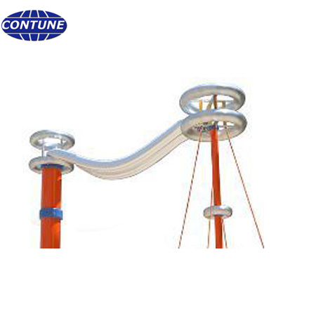
Test equipment for electrical tests of overhead line insulators. This test machine tests high voltage insulators with power voltage and frequency. The power frequency tests are required in IEC, ANSI, or any other technical standards for insulators of OHTL.
Insulator power frequency test equipment at a glance
- Purpose: generates a continuously adjustable AC test voltage at service frequency (50 Hz or 60 Hz) and applies it to overhead line insulators.
- Tests covered: power frequency withstand test, dry flashover test, wet flashover test and puncture test.
- Test objects: porcelain, glass, polymer (composite) and epoxy insulators for overhead transmission and distribution lines above 1000 V.
- Standards: IEC 60060-1 and IEC 60060-2 for the test technique; the power frequency tests prescribed by IEC 60383-1 and IEC 61109, or by the ANSI C29 series where specified.
- Reference configurations: 250 kV / 100 kVA for 11-66 kV insulators and 500 kV / 500 kVA for the 550 kV class; other ratings engineered to order.
- Users: insulator manufacturers, high-voltage laboratories, power research institutes and transmission utilities.
1. What this equipment is used for
The insulator power frequency test equipment produces a continuously adjustable alternating voltage at service frequency (50 Hz or 60 Hz) and applies it to overhead line insulators. Its job is to verify the electrical performance of an insulator at the voltage and frequency it sees in service, and to give a pass or fail result for the electrical part of type tests, sample tests, routine tests and incoming acceptance inspection.
It is used on porcelain, glass, polymer (composite) and epoxy-resin insulators for overhead transmission and distribution lines above 1000 V, and on other high voltage insulation within its rated voltage, such as bushings, instrument transformers and switchgear. The rated voltage and the capacity are engineered to the highest test voltage the applicable standard requires and to the layout of the laboratory.
2. Standards applied
The test voltages, the procedure and the acceptance criteria are taken from the standard that applies to the insulator being tested and from the project specification. The equipment itself is built to the high voltage test technique standards:
- IEC 60060-1 – High-voltage test techniques, Part 1: general definitions and test requirements.
- IEC 60060-2 – High-voltage test techniques, Part 2: measuring systems.
- IEC 60383-1 – Insulators for overhead lines with a nominal voltage above 1000 V, Part 1: ceramic or glass insulator units for a.c. systems – definitions, test methods and acceptance criteria. It specifies the power frequency tests for ceramic and glass units.
- IEC 61109 – Composite suspension and tension insulators for overhead lines with a nominal voltage above 1000 V.
- GB/T 16927.1 and GB/T 16927.2 – the Chinese national equivalents of IEC 60060-1 and IEC 60060-2.
- ANSI C29 series – applied instead of IEC where the purchaser specifies ANSI requirements; the same tests are then run with the ANSI voltages and procedure.
3. Power frequency tests performed
Four power frequency tests are used on overhead line insulators. Which of them are carried out, and whether as a type test, a sample test or a routine test, is defined by the applicable standard:
- Power frequency withstand test – the specified voltage is applied for the specified time; the sample passes when no flashover and no puncture occurs.
- Dry flashover test – the voltage is raised on a clean, dry insulator until it flashes over, and the flashover voltage is recorded.
- Wet flashover test – the same measurement with the insulator wetted by a standardised artificial rain. The wet value is lower than the dry value and is the one that governs the external insulation design of an outdoor insulator.
- Puncture test – the solid dielectric itself is stressed until breakthrough. It checks the internal insulation of ceramic and glass parts.
Flashover and puncture are two different failure modes: flashover is a discharge along the surface of the insulator, while puncture is a breakdown through the solid material between the electrodes. A complete laboratory therefore needs both capabilities.
4. Typical configurations and technical parameters
A power frequency test set is specified by two figures: the rated output voltage in kV, and the rated capacity in kVA that supplies the capacitive charging current at that voltage. The two reference configurations below cover the usual range of overhead line insulator testing; other combinations are engineered to order.
| Reference model | Rated output voltage | Rated capacity | Rated output current | Typical application |
|---|---|---|---|---|
| CTPF-50/150 | 150 kV | 50 kVA | 0.333 A | Power frequency withstand, flashover and puncture tests on 11 kV – 33 kV line and station insulators |
| C-PFWT-100/200 | 200 kV | 100 kVA | 0.5 A | Power frequency and partial discharge tests on insulators, arresters and cable accessories up to 66 kV |
| CT-EPFT-100/250 | 250 kV | 100 kVA | 0.4 A | Power frequency tests on 11 kV – 66 kV overhead line and station insulators |
| CTPF-150/300 | 300 kV | 150 kVA | 0.5 A | Power frequency withstand tests on insulators up to the 220 kV – 330 kV class |
| CT-EPFT-500/500 | 500 kV | 500 kVA | 1 A | Power frequency tests on insulators and bushings up to the 550 kV class |
| Other ratings | 150 kV – 500 kV | Matched to the capacitive load of the test object | 0.333 A – 1 A | Engineered to the laboratory layout and project specification |
General characteristics of the reference configurations:
- Single phase, 50 Hz (60 Hz on request), supply voltage 0.38 kV.
- Voltage ratio of the measuring winding and of the capacitive voltage divider: 1000 : 1.
- Waveform distortion not more than 3% at rated output.
- Short-circuit impedance not more than 6%.
- Partial-discharge-free construction; partial discharge can be measured through the coupling capacitor.
- Insulation level: 110% of rated voltage for 1 minute.
- Duty: 1 hour at rated voltage and rated current for the 150 kV configuration and 60 minutes for the 200 kV configuration; continuous operation at 80% of rated voltage and current. Winding temperature rise below 65 K and oil surface temperature rise below 55 K.
- Site conditions: altitude up to 1000 m, ambient temperature -10 degrees Celsius to +40 degrees Celsius, relative humidity up to 85%, independent earthing with an earth resistance below 0.5 ohm.
5. Key functions
- Continuously adjustable AC test voltage, from zero up to the rated voltage, at power frequency.
- Automatic voltage rise, holding and return, with the starting voltage, the rate of rise and the withstand time set by the operator.
- Segmented voltage-raising curve: several stages, each with its own target voltage and dwell time. Settings are saved as recipes and recalled for the next test.
- Digital measurement and display of the test voltage and of the test current through the capacitive voltage divider.
- Automatic test sequence – the operator mounts the sample and starts the test; the set runs the preset programme, stores the data and prints the report.
- Over-voltage protection, over-current protection, emergency stop, door interlock and earthing interlock.
- Manual control, or automatic control from a PLC and touch screen console with animated equipment status.
- Optional partial discharge measurement, using the capacitive voltage divider as a coupling capacitor.
- Safety arrangements for the test area: protective barriers, warning signs, warning lights, and optional video monitoring of the test bay.
6. Typical applications
- Insulator manufacturers – type tests, sample tests and routine electrical inspection of porcelain, glass and composite insulators.
- High voltage laboratories and power research institutes – research tests, special tests and third party verification.
- Power utilities and project owners – acceptance testing and incoming inspection.
- Other high voltage insulation – bushings, instrument transformers and switchgear within the rated voltage of the set.
7. Frequently asked questions
1. What is a power frequency withstand test on an insulator?
The specified AC voltage at service frequency is applied to the insulator for the specified time, normally one minute. The sample passes when no flashover along the surface and no puncture through the solid material occurs during that time.
2. What is the difference between flashover and puncture?
Flashover is a discharge that travels along the surface of the insulator between the electrodes, and the insulator usually recovers afterwards. Puncture is a breakdown through the solid dielectric body of the insulator, which permanently damages the part.
3. Why is a wet flashover test needed in addition to the dry test?
Outdoor insulators operate in rain. Wetting the insulator surface with a standardised artificial rain gives a much lower flashover voltage than the dry condition, so the wet value is the one used for the external insulation design of the line.
4. Which insulator types can be tested on this equipment?
All types of high voltage overhead line insulators: porcelain insulators, glass insulators, polymer (composite) insulators and epoxy-resin insulators.
5. How do I choose the rated voltage and the capacity?
The rated voltage is chosen from the highest power frequency test voltage the applicable standard and the project specification require, plus margin. The capacity is then chosen from the capacitive charging current of the test object at that voltage, which is why reference sets are rated between 0.4 A and 1 A. As a guide, 250 kV / 100 kVA covers 11 kV to 66 kV insulators and 500 kV / 500 kVA covers the 550 kV class.
6. Can the set run partial discharge measurement and 60 Hz tests?
Yes. The capacitive voltage divider can be used as a coupling capacitor for partial discharge measurement, and the set can be built for 60 Hz as well as 50 Hz when the laboratory supply and the standard require it.
Related insulator test equipment
This power frequency test equipment belongs to the electrical test equipment for insulators range. Contune also supplies the RIV test system for IEC 60437 radio interference measurement and the combined electro-mechanical strength tester for combined electrical and mechanical loading of disc insulator units. Browse the full insulator testing machines catalogue for mechanical and electrical test solutions.
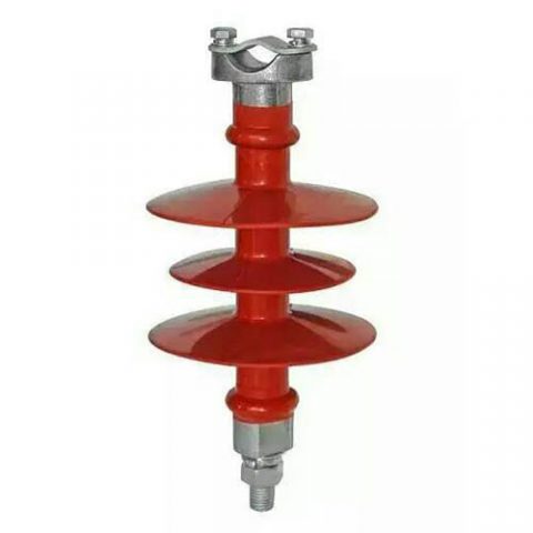
11 kV Composite Pin Insulator for Overhead Distribution Lines
11KV composite pin insulators are used on 11KV high voltage overhead power distribution lines. These pin insulators are made by FRP core, silicon rubber, and metallic fittings. On the bottom side of the fitting, it is where we call pin, the pin has a screw which is used to fix the insulator onto the cross-arm. On header fitting, it usually has a groove shape to fix conductors.