


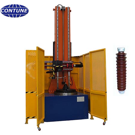
A combined tensile, cantilever and torsion test machine can reduce laboratory floor space and share control hardware, but it also creates a more demanding acceptance task. Each loading mode has a different force path, fixture, zeroing method and safety risk. A single statement that the machine “works” does not prove that all three modes are suitable for the buyer’s insulators.
Contune brochure data for the CTLWN500 provides a concrete reference configuration: 2000mm valid tensile test length, 300kN maximum tensile load, 20kN maximum cantilever load, 5kN·m maximum torsion, computer control and programmable test procedures. The brochure also lists ball-and-socket fitting connection. These values describe this model reference; usable specimen dimensions, adapters and test sequences must be confirmed from drawings and applicable standards.
Create a separate acceptance sheet for each axis
Tensile force, transverse cantilever force and torque should not be combined into one generic checklist. For each mode, define measuring range, target points, allowable indication error, loading direction, control rate, hold time, protection threshold and report fields. Identify the load cell or torque transducer and its calibration certificate.
Verify fixtures and the real force path
Fixtures should load the intended metal fitting without introducing unintended bending or torsion. Ball-and-socket adapters, post-insulator bases, lever arms and torque couplings need individual drawings and rated capacities. During FAT, record alignment, lever-arm length and adapter identification. Torque calculation is only meaningful when the effective arm or transducer arrangement is known.
Check the specimen envelope, not only rated load
The 2000mm valid tensile length is as important as the 300kN rating. Send minimum and maximum specimen length, shed diameter, base size, terminal geometry and required movement. A machine can have enough force but insufficient clearance, stroke or fixture adjustment for the actual sample.
Program a representative sequence
Use a buyer-approved procedure during FAT: preload, ramp, target, hold, unload and stop criteria. If the system supports programmable procedures, save and recall at least one sequence for each loading mode. Verify that a paused or aborted test preserves the event, measured value and termination reason rather than producing a clean but incomplete report.
Confirm cross-axis behavior and zeroing
Before each mode, inspect mechanical zero, sensor zero and unloaded fixture weight. Check whether changing fixtures influences another channel or requires a new tare. For combined loading projects, define whether loads are applied sequentially or simultaneously; do not assume simultaneous control from separate maximum ratings unless it is explicitly included in the engineering scope.
Safety and reporting requirements
Guard the specimen, couplings and lever arms, establish an exclusion zone and test emergency stop and over-range protection in every mode. The report should include sample identity, fixture, sensor, calibration, program version, time history, peak, hold period, displacement or angle, alarms and operator. Raw data export should be demonstrated during commissioning.
Buyer acceptance checklist
- Sample drawings and loading modes
- Tensile, cantilever and torque ranges
- Valid length, clearance, stroke and rotation
- Fixture drawings and rated capacities
- Sensor calibration for each axis
- Control rate, hold time and stop criteria
- Saved procedures and interruption records
- Guards, emergency stop and exclusion zone
- Curves, raw data and signed reports
FAQ
Can the maximum tensile and torsion ratings be used at the same time?
Not unless simultaneous combined loading is explicitly designed, specified and verified. Separate ratings alone do not prove a simultaneous-load envelope.
Why verify the lever arm during cantilever testing?
The applied moment depends on force and effective distance. An incorrect arm length changes the mechanical result even when the force reading is accurate.
Should FAT use a real insulator?
A representative specimen or equivalent fixture is strongly preferable because it exposes clearance, alignment, handling and reporting issues before shipment.
Related resources: cantilever and torsion tester, testing machines, project inquiry.