


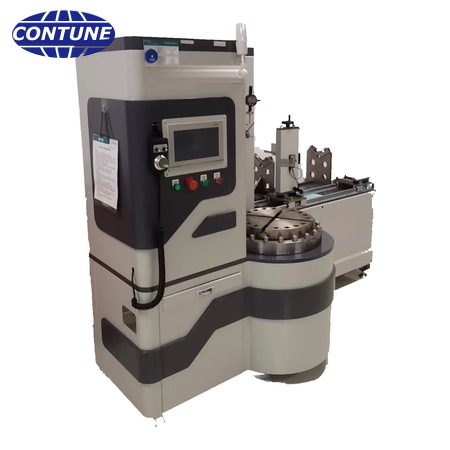
To specify a post-insulator deviation inspection platform, send drawings of both fixing flanges and the complete insulator envelope before choosing a fixture. Confirm the upper and lower bolt-circle geometry, structural height, shed diameter, measurement datums and required report fields. A platform may have enough height but still be unable to locate a flange or measure a shed without the correct adapter.
The Contune CT-PD26 product page describes separate vertical and horizontal measuring modules. The vertical module handles parallelism, eccentricity, camber and shed angle; the horizontal module handles fixing-hole angular deviation, structural height and shed diameter. The page cites IEC 60168 Annex A and GB/T 8287.1-2008. The IEC 60168 publication scope covers ceramic or glass post insulators for AC installations above 1,000 V. Confirm the edition, actual test method and contractual tolerances rather than treating the machine’s indicator resolution as a pass/fail limit.
Which drawings belong in the RFQ?
Provide a dimensioned drawing of each post-insulator family: total structural height, maximum shed diameter, upper and lower flange outside diameters, bolt-circle diameters, hole count and size, and hole orientation. Include the surface or axis used as the datum for parallelism, eccentricity and camber. Specify whether each end uses a flange, stud or other fitting. Ask the supplier to mark how the specimen will be clamped, rotated and referenced; a generic nominal voltage class is not enough to design the adapter.
Check each module against the largest specimen
| Product-page figure | CT-PD26 vertical module | CT-PD26 horizontal module |
|---|---|---|
| Fitting flange | Up to 400 mm diameter | Up to 600 mm diameter |
| Structural height | Effective space 1,000 mm, stated as customizable | Digital measurement 0–1,000 mm |
| Shed diameter | Confirm access with the supplier | Digital measurement 0–500 mm |
| Angular / deviation indication | Shed angle 0–90°, stated accuracy 0.1°; four 25.4 mm digital indicators, stated accuracy 0.01 mm | Inclinometer 4 × 90°, stated accuracy ±0.2° |
These are published equipment figures, not guaranteed fit for every shape. The vertical flange limit differs from the horizontal limit; do not use the 600 mm horizontal figure to approve a 500 mm flange on the vertical module. The product page lists Modbus-RTU or Modbus-TCP for data upload. Confirm interface registers, sample identifiers and exported fields if the laboratory must connect to a quality system.
Witness a useful factory acceptance test
- Mount representative smallest and largest posts using the quoted adapters; inspect clearance throughout rotation and lifting.
- Establish the drawing datums and record the zeroing and alignment method for every indicator.
- Repeat a specimen setup and record raw readings plus calculated parallelism, eccentricity, camber and shed angle.
- Verify fixing-hole orientation, height and diameter on the horizontal module.
- Export a report tied to specimen ID, drawing revision, instrument IDs and calibration evidence; test motion limits and safe stop.
Agree repeatability criteria and dimensional acceptance limits before the FAT. The vendor’s 0.01 mm and 0.1° figures are product-page claims that need calibration and whole-fixture verification; they are not a substitute for an uncertainty assessment. For disc-type units, use a separate disc-insulator fixture and measurement method.
FAQ
Can the horizontal module’s 600 mm flange capacity be applied to the vertical module?
No. The published vertical figure is 400 mm. Request a custom adapter or engineering review for larger vertical flanges.
Does a 1,000 mm structural-height figure guarantee that my post fits?
No. End fittings, clamping and movement clearance must also fit the actual drawing.
Is the platform intended for disc insulators?
The CT-PD26 page describes post insulators. Disc units have different datums and a separate checking device.