


Post Insulator Dimensional Deviation Inspection Platform (Parallelism, Eccentricity, Camber & Shed Angle Tester) — GB/T 8287.1 / IEC 60168 Annex A
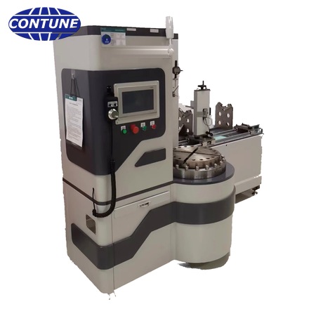
The CT-PD26 post insulator dimensional deviation inspection platform carries out the shape and position deviation checks of GB/T 8287.1-2008 Annex A (IEC 60168 Annex A) on post insulators up to 1000 mm structural height: parallelism, eccentricity, camber, shed angle, angular deviation of the fixing holes, structural height and shed diameter, with a vertical measuring module and a horizontal measuring module.
The CT-PD26 post insulator dimensional deviation inspection platform performs the shape and position deviation checks required by GB/T 8287.1-2008, Annex A — Methods of checking the shape and position deviations of post insulators, which corresponds to IEC 60168, Annex A (Methods of testing for tolerances of parallelism, eccentricity, angular deviation, camber, and shed angle of post insulators) and to IEC 60168, Clause 5.1, Verification of the dimensions — type and sample test. One platform, built from a vertical measuring module and a horizontal measuring module, checks a post insulator up to 1000 mm structural height for parallelism, eccentricity, camber, shed angle, angular deviation of the fixing holes, structural height and shed diameter. It is used by post insulator manufacturers, electric power companies and electrical testing laboratories for sample tests and routine dimensional inspection.
Why must the shape and position deviations of a post insulator be checked?
Annex A of IEC 60168 / GB/T 8287.1 specifies the methods for checking the tolerances of parallelism, eccentricity, angular deviation, camber and shed angle of post insulators. If any of these deviations exceeds the tolerance, the insulator cannot be assembled correctly on the structure, the fixing holes will not match the stand-off fittings, and the specified creepage and clearance distances may not be maintained. The dimensional verification of Clause 5.1 is therefore a type test and sample test that every post insulator design must pass before delivery.
What does the CT-PD26 check?
One platform covers the complete shape and position deviation check of a post insulator:
- Parallelism of the end faces
- Eccentricity — maximum deviation between the axes of the upper and lower fixing-hole centre circles
- Camber (straightness) of the insulator axis
- Shed (umbrella) angle
- Angular deviation of the fixing holes
- Structural height
- Shed diameter
The measuring data of the parallelism, eccentricity, camber and shed angle checks can be uploaded through serial Modbus-RTU or Ethernet Modbus-TCP.
Vertical measuring module
The vertical module performs the parallelism, eccentricity, camber and shed angle checks, supported by the dedicated measuring software. It accepts post insulators with metal fitting flange diameters up to φ400 mm and structural heights up to 1 m (customisable). The turntable rotates 360° without limit, and the measuring unit travels vertically over the full 1 m height (installation dimensions and measuring height can be customised). The turntable is supplied with T-slots, threaded holes or an adapter plate made to the customer’s flange drawing. Digital dial indicators with a range of ±25.4 mm (customisable) measure the horizontal and axial deviations with automatic deviation calculation; the data can also be collected by cable and transmitted to the control system in real time. One run automatically acquires the four test data sets, controls the test sequence and produces the statistics at the end of the test. Motion limits are protected and the protection threshold is configurable.

Horizontal measuring module
The horizontal module performs the angular deviation of the fixing holes, the structural height and the shed diameter checks, with digital read-out. The main machine is built on a welded frame machined on a CNC milling machine and fitted with precision linear guides; it integrates the measuring unit, lifting unit, digital inclinometer, guards, machine fixings and supporting device, and rides on levelling castors so it can be moved to a suitable measuring position. All indicating devices are battery powered and digital.

Technical parameters
The complete specification of both modules, the communication interfaces and the scope of supply are listed under the Technical Info tab.
Standards applied
- GB/T 8287.1-2008 Indoor and outdoor post insulators of ceramic material or glass for systems with nominal voltage greater than 1000 V — Part 1: Tests, Annex A — shape and position deviation check methods
- IEC 60168 Tests on indoor and outdoor post insulators of ceramic material or glass for systems with nominal voltages greater than 1000 V, Annex A — tolerances of parallelism, eccentricity, angular deviation, camber and shed angle; Clause 5.1 — verification of the dimensions
Vertical measuring module
| Turntable diameter | φ400 mm |
| Effective space (structural height) | 1000 mm (customisable) |
| Admissible fitting flange diameter | up to φ400 mm |
| Turntable speed | 0–2 rpm, steplessly adjustable |
| Lifting speed | 500 mm/min |
| Turntable flatness | 0.1 mm |
| Concentricity of the rotation centre | 0.1 mm |
| Control | computer control / manual reading |
| Product fixing | T-slots, threaded holes or adapter plate (made to the customer’s flange drawing) |
| Shed angle measurement | 2500-line rotary encoder, 0–90°, accuracy 0.1° |
| Other deviation measurement | four digital dial indicators, range 25.4 mm, accuracy 0.01 mm, with automatic deviation calculation |
| Data acquisition | one run automatically acquires parallelism, eccentricity, camber and shed angle, controls the test sequence and prints the statistics |
| Communication | Modbus-RTU / Modbus-TCP |
| Protection | motion limits with configurable protection thresholds |
| Upper flange locating plate | precision-machined, wear-resistant measuring surface |
Horizontal measuring module
| Overall dimensions | 1500 × 560 × 1450 mm |
| Measuring angle range | 4 × 90° |
| Measuring accuracy / repeatability | ±0.2° / 0.1° |
| Digital inclinometer power supply | 9 V zinc-manganese battery |
| Lifting scale travel | 0–300 mm, resolution 0.01 mm / 0.0005″ (3 V CR2032 battery) |
| Admissible fitting flange diameter | up to 600 mm |
| Structural height measurement | 0–1000 mm (digital caliper) |
| Shed diameter measurement | 0–500 mm (digital caliper, 600 mm long jaw) |
| Frame | welded frame, CNC-machined surfaces, precision linear guides, levelling castors |
Scope of supply
| Vertical module | vertical main machine (effective height 1000 mm), 1 set; lifting unit (lead screw, motor, reducer, guides), 1 set; rotating unit (φ400 turntable, motor, reducer, angle encoder), 1 set; shed angle measuring unit (measuring rod, angle encoder), 1 set; digital dial indicators 25.4 mm, 4 pcs; operating console with computer and dedicated software, optional, 1 set; T-slots M10/M12/M14/M16 with 30 mm bolts, 8 pcs each; upper flange locating plate made to the customer’s drawing, 1 pc |
| Locating and clamping parts | locating pins φ14 / φ18 / φ24 / M12 / M16 / M20, 10 pcs each; taper-shank bolts M12 / M16 / M20, 6 pcs each; taper-shank nuts M12 / M16 / M20, 6 pcs each |
| Horizontal module | horizontal main machine (frame, handwheel), 1 unit; digital inclinometer 4 × 90°, 1 set; structural height digital caliper 1000 mm, 1 set; shed diameter digital caliper with 600 mm long jaw, 1 set |
| Documentation | user manual, certificate of conformity, packing list, factory test report and warranty card, one copy each |
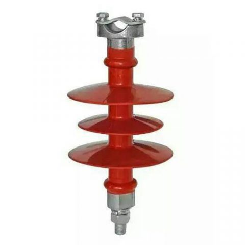
11 kV Composite Pin Insulator for Overhead Distribution Lines
11KV composite pin insulators are used on 11KV high voltage overhead power distribution lines. These pin insulators are made by FRP core, silicon rubber, and metallic fittings. On the bottom side of the fitting, it is where we call pin, the pin has a screw which is used to fix the insulator onto the cross-arm. On header fitting, it usually has a groove shape to fix conductors.