


Insulator Locking Pin Testing Machine (Cotter Pin Tester) for Ball & Socket Couplings
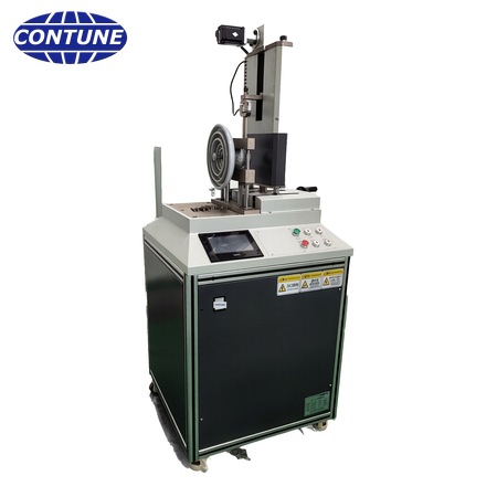
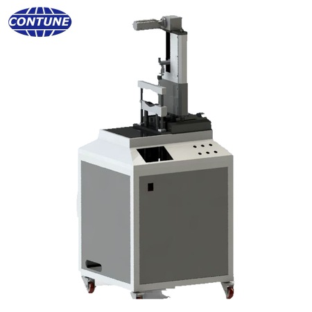
The CT-LP26 locking pin testing machine verifies the locking system of insulator ball and socket couplings to IEC 60383-1. Tensile load is applied along the pin axis until the pin slides; the peak load is recorded automatically.
The CT-LP26 locking pin testing machine — also called cotter pin tester — verifies the locking system of insulator ball & socket couplings in accordance with IEC 60383-1. The tensile load is applied along the axis of the locking pin and is increased gradually until the pin slides out of its seat, and the peak load is recorded automatically. It is used by manufacturers of glass disc insulators, porcelain disc insulators and composite insulators, as well as by electrical testing laboratories and power utilities.
What is a locking pin (cotter pin) of an insulator?
The locking pin — also called cotter pin or locking clip — is the small but decisive part of an insulator string with ball & socket coupling. It locks the connection between the insulator units and the metal fittings and prevents the coupling from sliding out of its seat.
What does the locking pin test verify?
In IEC 60383-1 the corresponding sample test is the verification of the locking system: the locking pin shall withstand the specified tensile load applied along the axis of the pin without sliding out of the coupling. On the CT-LP26 the load is applied along the pin axis and is increased gradually until the pin starts to slide, so the ultimate value is measured and recorded as the test result.
How is the tensile load applied to an R-pin and to a W-pin?

For an R-pin, a suitable device applies the tensile load along the axis of the pin on the eye of the pin.

For a W-pin, a rectangular steel bar of section F5×T as specified in JB/T 8181 applies the load along the axis on the two arc ends of the W-shaped pin.
Which insulators can be tested?
One machine covers the locking pins of insulator units of 70 kN, 120 kN, 210 kN, 300 kN, 420 kN and 550 kN, that is the pin designations 16, 20, 24, 28, 32 and 36 as specified in JB/T 8181.
- Glass disc insulator and porcelain (ceramic) disc insulator — one unit, or two units coupled in series
- Composite (polymeric) tension insulator — locking system of a single insulator
How is the machine built?
The main frame is built from industrial aluminium profile and assembled from welded, drilled and milled parts, which keeps the machining accuracy and makes installation simple. The tension unit consists of hook, load cell, hand wheel and precision linear bearing; the moving and positioning device uses a mini hand wheel with a high accuracy linear guide. A well-known brand PLC and an all-in-one touch screen terminal give accurate counting and simple operation, and the peak value is shown directly on the screen. A protection guard and a complete safety control and protection system keep both the operator and the equipment safe under all working conditions.
Who uses this locking pin tester?
It is used by manufacturers of glass disc insulators, porcelain disc insulators and composite insulators, and by electrical testing laboratories and power utilities for type, sample and routine verification of the insulator locking system.
After-sales service
- One year warranty for the equipment
- Permanent free software upgrade
- 3-year free technical support; payable technical consulting service from the 4th year
About Contune International Co., Ltd
Contune International Co., Ltd designs and manufactures testing machines and production machines for the electrical insulator industry. With machinery engineers and technicians experienced in insulator production, we understand insulators and the relevant standards, and our testers are built for the test procedures of IEC, ANSI, BS and DIN standards.
Standards applied
- IEC 60383-1 — Insulators for overhead lines with a nominal voltage above 1000 V — Part 1: Ceramic or glass insulator units for a.c. systems — Definitions, test methods and acceptance criteria (verification of the locking system)
- JB/T 8181-1999 — Locking pins for ball and socket couplings of string insulator units
- GB/T 4056-2008 — Connecting dimensions for ball and socket couplings of string insulator units
- GB/T 1001.1-2003 — Insulators for overhead lines with a nominal voltage above 1000 V — Part 1: Ceramic or glass insulator units for a.c. systems — Definitions, test methods and acceptance criteria
- GB/T 19443-2004 — Insulators for overhead lines with a nominal voltage above 1000 V — Ceramic or glass insulator units for d.c. systems — Definitions, test methods and acceptance criteria
- GB/T 19519-2004 — Composite insulators for a.c. overhead lines with a nominal voltage greater than 1000 V — Definitions, test methods and acceptance criteria
Test procedure
The tensile load is applied along the axis of the locking pin and is increased gradually until the pin slides out of its seat. For an R-pin the load acts on the eye of the pin; for a W-pin a rectangular steel bar of section F5×T (JB/T 8181) acts on the two arc ends of the W-shaped pin. The peak load is captured and displayed automatically, so the sliding value is read directly without manual judgement.
Technical specifications
| Model | CT-LP26 |
| Type of test | Mechanical strength test — verification of the locking system |
| Measuring range of load | 1 – 3000 N |
| Load indication accuracy | ±1 % |
| Load resolution | ±500,000 digits |
| Peak load record | Yes |
| Max. stroke of the pull-out pin | 300 mm |
| Applicable pin designations | 16, 20, 24, 28, 32, 36 (JB/T 8181) |
| Applicable insulator units | 70 kN, 120 kN, 210 kN, 300 kN, 420 kN, 550 kN |
| Applicable specimens | Ceramic and glass insulators, one unit or two units in series; locking system of a single composite insulator |
| Control system | Brand PLC with all-in-one touch screen terminal |
| Main construction | Industrial aluminium profile frame; moving & positioning device; protection guard; product fixing part; tension unit (hook, load cell, hand wheel, precision linear bearing) |
| Safety protection | Protection guard with complete safety control and protection system |
| Dimension of equipment (L×W×H) | 700 × 700 × 1800 mm |
| Net weight | About 150 kg |
| Power supply | AC 220 V, 1 kW |
| Ambient conditions | Working temperature −20 °C to 50 °C; stable 220 V a.c. supply; indoor location with good ventilation |
| Supply scope | Equipment frame — 1 set; load cell — 1 set; control system — 1 set; accompanying documents — 1 set |
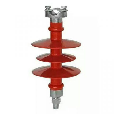
11 kV Composite Pin Insulator for Overhead Distribution Lines
11KV composite pin insulators are used on 11KV high voltage overhead power distribution lines. These pin insulators are made by FRP core, silicon rubber, and metallic fittings. On the bottom side of the fitting, it is where we call pin, the pin has a screw which is used to fix the insulator onto the cross-arm. On header fitting, it usually has a groove shape to fix conductors.