


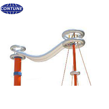
A wet flashover test room is a coordinated high-voltage system, not simply a test transformer placed beside a spray rack. The buyer must align the insulator drawing, required test voltage, source capacity, measuring divider, protective resistor, grounding, control boundary and water-handling interfaces before the civil layout is frozen.
Contune sample specifications describe a 150kV/50kVA AC system for 33kV glass, porcelain and polymer insulators and a 250kV/100kVA system for 11kV to 66kV products. Both cite IEC 60060-1:2010 and IEC 60060-2:2010. These are equipment references for preliminary planning; the final rating must be confirmed from the applicable product standard, test object capacitance and required wet-test procedure.
Start with the test object and required procedure
Provide the insulator type, voltage class, dry arcing distance, overall dimensions, coupling arrangement and intended mounting orientation. State whether the laboratory must perform wet flashover, dry flashover, power-frequency withstand or puncture tests. The required procedure determines clearances, fixture geometry, water collection and the operating sequence.
Treat the AC source, resistor and divider as one system
The 150kV example lists 50kVA output, 0.333A, single-phase 50Hz and a 1000:1 voltage ratio. Its protective resistor is listed at 150kV, 0.33A and 5kΩ, with a 150kV, 300pF ±2% capacitive divider. The 250kV example lists 100kVA, 250kV and 0.4A, with a 250kV, 5kΩ resistor and 250kV, 300pF ±2% divider. Layout drawings should reserve safe positions and connection routes for every component.
Separate the energized zone from the operator
The control console belongs outside the restricted high-voltage area. Access doors, warning signals, emergency stop, grounding switch and interlocks should follow a documented operating sequence. The purchase specification should identify which protections are hardware based and which are implemented through control software.
Plan wet-test utilities without inventing the spray specification
The AC equipment brochure confirms wet flashover capability, but it does not define the buyer’s complete spray arrangement. Water conductivity, precipitation rate, nozzle layout, collection and drainage should therefore be specified from the applicable test standard and laboratory procedure. Provide clean-water supply, drainage, corrosion-resistant routing and enough service access to inspect nozzles without entering an energized setup.
Grounding and clearance need a site drawing
Send room dimensions, door positions, ceiling height, structural metalwork and the proposed grounding network. Include the transformer, divider, resistor, test object, spray frame, barriers and control console on one scaled drawing. Final electrical clearances and grounding details should be approved by the responsible high-voltage engineer for the installation site.
RFQ and acceptance checklist
- Insulator drawings, voltage class and mounting orientation
- Applicable test standard and wet-test procedure
- Maximum test voltage, source kVA and expected test-object capacitance
- Transformer, protective resistor and divider ratings
- Room dimensions, access, grounding and safety boundary
- Water supply, conductivity control, spray frame and drainage interfaces
- Control, interlocks, calibration, commissioning and report format
FAQ
Is 150kV automatically sufficient for every 33kV insulator?
No. Confirm the required test voltage, object capacitance, procedure and margin from the relevant product standard and sample drawing.
Can the spray system be added after installation?
It can be retrofitted, but planning it early improves clearance, drainage, corrosion control and operator access.
What should be witnessed during acceptance?
Verify voltage measurement, protection operation, grounding sequence, interlocks, control records and the agreed wet-test procedure with a representative sample.
Related resources: power-frequency test equipment, laboratory planning, project inquiry.