


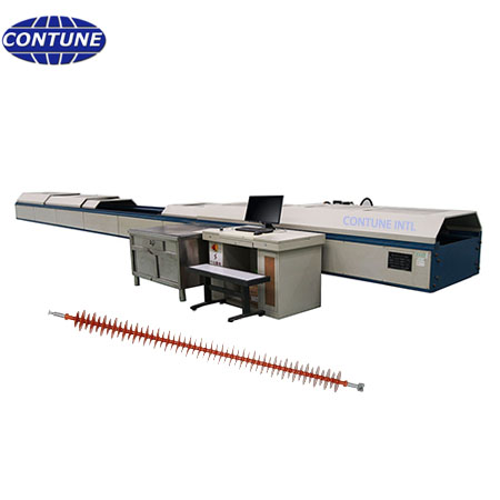
A thermal-mechanical test report for string insulators must prove more than a final pass or fail. It should show that the specimen experienced the specified tensile load while the chamber completed the required heating and cooling sequence, with enough time-stamped data to investigate any interruption.
Contune brochure data for vertical and horizontal thermal-mechanical test machines provides useful planning references. The cited procedure uses four 24-hour heating and cooling cycles and a tensile load equal to 60% of the specified electromechanical or mechanical failing load. Applicable references listed in the material include GB/T 19519-2004, IEC/TR 60575:1997 and GB/T 22708-2008.
Record the test identity before the first cycle
The report header should identify the insulator type, drawing number, serial or batch number, overall length, coupling type and specified mechanical failing load. It should also identify the fixture set, load cell, temperature sensors, software version and calibration status. This information prevents a valid temperature chart from being attached to the wrong sample or fixture configuration.
Build a traceable four-cycle record
For each of the four 24-hour cycles, record the programmed high and low temperatures, actual chamber temperature, ramp and dwell periods, tensile load, start and finish time, and any pause or alarm. The report should preserve the time relationship between load and temperature. A separate temperature chart and load chart without synchronized timestamps makes root-cause review unnecessarily difficult.
Define load control and acceptance limits
The brochure procedure references 60% of the specified failing load. The purchase specification should also state allowable load deviation, how quickly load is restored after temperature movement, and what happens after a power interruption. The report should contain target load, measured minimum and maximum, deviations, alarm events and operator acknowledgements.
Match the machine configuration to the specimen
Vertical C-TMT configurations are listed with one to four workstations and up to 500kN tensile load. A horizontal C-TMT-1P/600H example lists one workstation, 600kN maximum tensile load, 300mm cylinder stroke and a 3000 × 1000 × 800mm inner chamber. These figures are configuration references, not universal limits. Buyers must confirm sample length, coupling geometry, thermal movement, working clearance and required load before ordering.
Include fixtures, safety and interruption records
Ball-and-socket or other specified couplings should be identified in the report. Fixture alignment, pin condition and pre-load should be checked before cycling. Door interlocks, over-temperature protection, load limits and emergency stops should be included in commissioning and periodic verification records. An interrupted cycle should never disappear from the report; record the cause, duration, temperature and load state, then document the agreed restart rule.
Buyer checklist for the report specification
- Sample drawing, length, coupling and failing load
- Applied standard and exact cycle profile
- Target load and allowable deviation
- Temperature sensor locations and logging interval
- Fixture identification and calibration records
- Alarm, interruption and restart history
- Raw data export, charts and signed summary
FAQ
Is a temperature chart alone a complete report?
No. The report should synchronize temperature, tensile load, cycle stage, alarms and specimen identity.
Can one machine test several insulator lengths?
Often yes, but chamber dimensions, cylinder stroke, fixture adjustment and thermal expansion must be checked against each drawing.
What should be sent with an RFQ?
Send drawings, coupling type, specified failing load, cycle profile, standard, workstation count, report format and available utilities.
Related resources: insulator testing machines, testing laboratory planning, project inquiry.